 Current Transformer Current Probe Current Transducer,
Current Toroid CT Current Sensor Pulse Current Monitor,
High Frequency Current Transformer
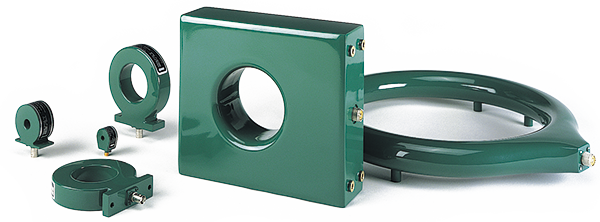
Whether you are interested in observing and measuring submilliamp currents in a charged particle beam or thousands of amps resulting from a fault in a major power feeder, you will find a Pearson current monitor to suit your needs. The use of our patented distributed termination technique permits pulse-current monitoring of rise times as short as two nanoseconds. Our current sensor devices of larger inner diameter make possible high voltage current measurement without the risk of voltage breakdown. Several of our current transformer models feature double shielding for greater noise immunity and increased safety in high voltage applications. All models are sealed and are suitable for use in high voltage insulating oil or under vacuum. They can be connected to oscilloscopes, spectrum analyzers, power analyzers, digital voltmeters, analog-to-digital convertors, and a variety of other measuring instruments.
|
|
Shape |
Output |
HoleId. |
Time Domain Parameters |
Frequency Domain Parameters |
||||||||
|
Max. |
Droop |
Useable Rise |
IT Max. |
Max. |
3dB pt. |
3dB |
I/f |
||||||
|
F |
1.0 |
0.25 |
100 |
200 |
2 |
0.0004** |
2.5 |
300 |
200 |
0.0025 |
|||
|
E |
1.0 |
0.5 |
500 |
90 |
10 |
0.002** |
5 |
140 |
35 |
0.006 |
|||
|
D |
1.0 |
2.0 |
500 |
80 |
20 |
0.005** |
7.5 |
125 |
20 |
0.017 |
|||
|
K |
1.0 |
2.0 |
500 |
300 |
1.5 |
0.002** |
10 |
400 |
250 |
0.008 |
|||
|
J |
1.0 |
3.5 |
500 |
140 |
3.5 |
0.01** |
10 |
200 |
120 |
0.04 |
|||
|
C |
1.0 |
3.5 |
500 |
40 |
50 |
0.03** |
12 |
40 |
7 |
0.1 |
|||
|
D |
0.5 |
2.0 |
1,000 |
20 |
20 |
0.02** |
15 |
40 |
20 |
0.07 |
|||
|
K |
0.5 |
2.0 |
1,000 |
100 |
2.5 |
0.008** |
20 |
100 |
200 |
0.03 |
|||
|
C |
0.25 |
3.5 |
2,000 |
100 |
30 |
0.09 |
60 |
160 |
10 |
0.6 |
|||
|
F |
0.1 |
0.25 |
400 |
20 |
5 |
0.004** |
10 |
30 |
70 |
0.025 |
|||
|
E |
0.1 |
0.5 |
5,000 |
60 |
20 |
0.25 |
50 |
120 |
20 |
1.7 |
|||
|
E |
0.1 |
0.5 |
5,000 |
0.9 |
20 |
0.2** |
50 |
1 |
20 |
0.6 |
|||
|
I |
0.1 |
1.0 |
5000 |
1 |
20 |
0.2 |
50 |
1 |
20 |
0.6 |
|||
|
D |
0.1 |
2.0 |
5,000 |
0.8 |
20 |
0.5** |
65 |
1 |
20 |
1.5 |
|||
|
D |
0.1 |
2.0 |
10,000 |
0.8 |
20 |
0.5** |
65 |
1 |
20 |
1.5 |
|||
|
K |
0.1 |
2.0 |
2,000 |
15 |
5 |
0.04** |
40 |
25 |
120 |
0.12 |
|||
|
C |
0.1 |
3.5 |
5,000 |
20 |
40 |
0.6 |
140 |
40 |
10 |
3.6 |
|||
|
A |
0.1 |
10.75 |
5,000 |
250 |
50 |
0.7** |
120 |
400 |
7 |
4.4 |
|||
|
D |
0.025 |
2.0 |
20,000 |
100 |
100 |
0.5 |
100 |
160 |
4 |
3.0 |
|||
|
C |
0.025 |
3.5 |
20,000 |
4 |
100 |
3.0 |
325 |
7 |
4 |
20.0 |
|||
|
F |
0.01 |
0.25 |
2,000 |
2 |
20 |
0.04** |
25 |
3 |
20 |
0.25 |
|||
|
E |
0.01 |
0.5 |
25,000 |
0.3 |
20 |
0.5** |
100 |
0.5 |
20 |
3.0 |
|||
|
D |
0.01 |
2.0 |
50,000 |
0.1 |
100 |
2.5** |
200 |
0.25 |
4 |
12.0 |
|||
|
D |
0.01 |
2.0 |
20,000 |
0.3 |
25 |
1.0** |
150 |
0.5 |
15 |
3.5 |
|||
|
C |
0.01 |
3.5 |
50,000 |
3 |
200 |
22.0 |
400 |
5 |
2 |
140.0 |
|||
|
C |
0.005 |
3.5 |
200,000 |
2.0 |
250 |
25 |
750 |
3.0 |
1.5 |
150 |
|||
|
C |
0.005 |
3.5 |
100,000 |
1.0 |
250 |
65 |
1400 |
0.9 |
1.5 |
400 |
|||
|
D |
0.001 |
2.0 |
200,000 |
0.05 |
200 |
6.0** |
400 |
0.7 |
2 |
40 |
|||
|
C |
0.001 |
3.5 |
500,000 |
0.7 |
500 |
75 |
2500 |
1.0 |
1.2 |
450 |
|||
|
B |
0.001 |
4.75 |
500,000 |
0.09 |
2000 |
1200 |
2500 |
0.15 |
0.2 |
7500 |
|||
|
|
Accuracy +1%, -0% of initial pulse amplitude for all models, with a high impedance load such as 1 megohm in parallel with 20 pF. A 50 ohm termination will reduce the output to half.
* are double shielded and are recommended for high voltage or high noise environments. The entries labeled
** may need a small dc bias current through the secondary for maximum current-time rating.
† Type N Connector


